How to Draw State Diagram in Uml
Visio Programme 2 Visio Programme ane Visio Professional person 2021 Visio Professional 2019 Visio Professional person 2016 Visio Professional 2013 Visio Premium 2010 Visio 2010 More than...Less
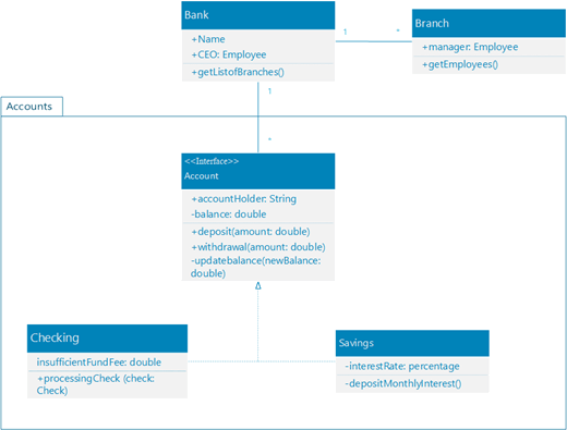
Y'all tin can create a UML form diagram to show a static view of a arrangement's classes, their attributes and methods, and the relationships among objects. Information technology gives an overview of an application.
(The Professional editions of Visio include support for the UML Class diagram and stencil, but the Standard editions don't.)
When you showtime a new class diagram, the UML Class stencil appears, along with shapes that adapt to the UML two.5 standard.
-
Offset Visio. Or if you have a file open already, click File > New.
-
In the Search box, type UML class.
-
Select the UML Class diagram.
-
In the dialog box, select the bare template or one of the iii starter diagrams. (A clarification of each one is shown on the right when you select it.) Then select either Metric Units or U.s.a. Units.
-
Select Create.
-
The diagram opens. You lot should see the Shapes window next to the diagram. If you don't come across it, get to View > Task Panes and make sure that Shapes is selected. If you lot still don't see it, click the Aggrandize the Shapes window button on the left.
-
On the View tab, make sure the cheque box next to Connection Points is selected. This option makes connexion points appear when you start connecting shapes.
-
Now, drag shapes yous desire to include in your diagram from the Shapes window to the folio. To rename text labels, double-click the labels.
-
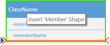
To add together more members to the class, enumeration or interface shape, drag the member shape from the shape console to the corresponding shape. Y'all can also add a new member by right-clicking an existing member and choosing the option to insert a member.
-
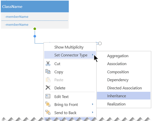
Connect two shapes with UML connectors to represent the relationships betwixt the shapes. To change the relationship types, correct-click the connector. Choose the desired human relationship from the Ready Connector Type menu.
-
Resize a class, enumeration, or interface shape by clicking the shape header to select it and and so moving the xanthous control betoken (on the right edge of the shape) left or correct to decrease or increase the width of the shape.
-
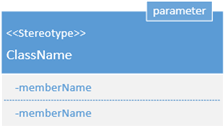
Add together parameter and stereotype fields to your grade shapes by selecting the shape, right-clicking and choosing the corresponding selection from the pop-upwardly bill of fare.
First, you create a diagram and add together a UML course stencil that has shapes that conform to the UML 2.five standard.
-
Open Visio for the spider web.
-
Near the upper right corner of the page, select More templates.
-
In the Gallery, scroll downwardly to the UML Course row, about midway down the page.
The first item in the row represents a blank template plus the companion stencil. The other items in the row are sample diagrams that have some shapes already drawn to help you get started quickly.
-
Click any detail to meet a larger preview.
-
When you notice the diagram you lot want to apply, click its Create button.
The new diagram, with the related stencil, opens in your browser. Y'all're ready to begin drawing your diagram.
-
Now, drag shapes yous want to include in your diagram from the Shapes window to the page. To rename text labels, double-click the labels.
-
To add more members to the class, enumeration or interface shape, drag the member shape from the shape panel to the corresponding shape. You can also add a new fellow member past right-clicking an existing member and choosing the selection to insert a fellow member.
-
Connect two shapes with UML connectors to represent the relationships betwixt the shapes. To modify the relationship types, correct-click the connector. Choose the desired human relationship from the Set Connector Type carte.
-
Resize a class, enumeration, or interface shape by clicking the shape header to select it so moving the yellow control point (on the right edge of the shape) left or right to decrease or increase the width of the shape.
-
Add parameter and stereotype fields to your class shapes by selecting the shape, right-clicking and choosing the respective selection from the pop-upwards card.
Beginning, yous select the UML Form diagram, which comes with a class stencil containing shapes that conform to the UML 2.0 specification.
-
First Visio. Or if yous have a file open already, click File > New.
-
In the Search box, type UML class.
-
Select the UML Grade diagram.
-
In the dialog box, select either Metric Units or U.s. Units.
-
Select Create.
-
The diagram opens. Yous should meet UML Class stencil in the Shapes window adjacent to the diagram. If yous don't encounter it, go to View > Task Panes and make sure that Shapes is selected. If you even so don't see it, select the chevron on the left margin of the window Expand the Shapes window button.
-
On the View tab, make sure the cheque box next to Connection Points is selected. This option makes connection points announced when you outset connecting shapes.
-
Now, drag shapes you desire to include in your diagram from the Shapes window to the page. To rename text labels, double-click the labels.
In Visio 2010, the fashion to create a UML class diagram is past using a Static Construction diagram. See Create a UML static construction diagram for details.
Tips for creating a grade diagram
-
Place each chemical element and its relationships.
-
Clearly identify what each class is responsible for.
-
Don't include unnecessary properties in the diagram that might brand it too complicated.
Class note
| Symbol | Meaning |
|---|---|
| - | The attribute or operation is individual. |
| + | The attribute or operation is public. |
Come across As well
UML diagrams in Visio
How to Draw State Diagram in Uml
Source: https://support.microsoft.com/en-us/office/create-a-uml-class-diagram-de6be927-8a7b-4a79-ae63-90da8f1a8a6b
0 Response to "How to Draw State Diagram in Uml"
Post a Comment